
Polykubos SGX motherboard installation
Step 1 – Prepare the donor board
Remove the HuCard ribbon cables first. They must come off before any other work so you have clear access to the board while de-soldering other parts. Carefully de-solder the ribbons from their pads, then set them aside.
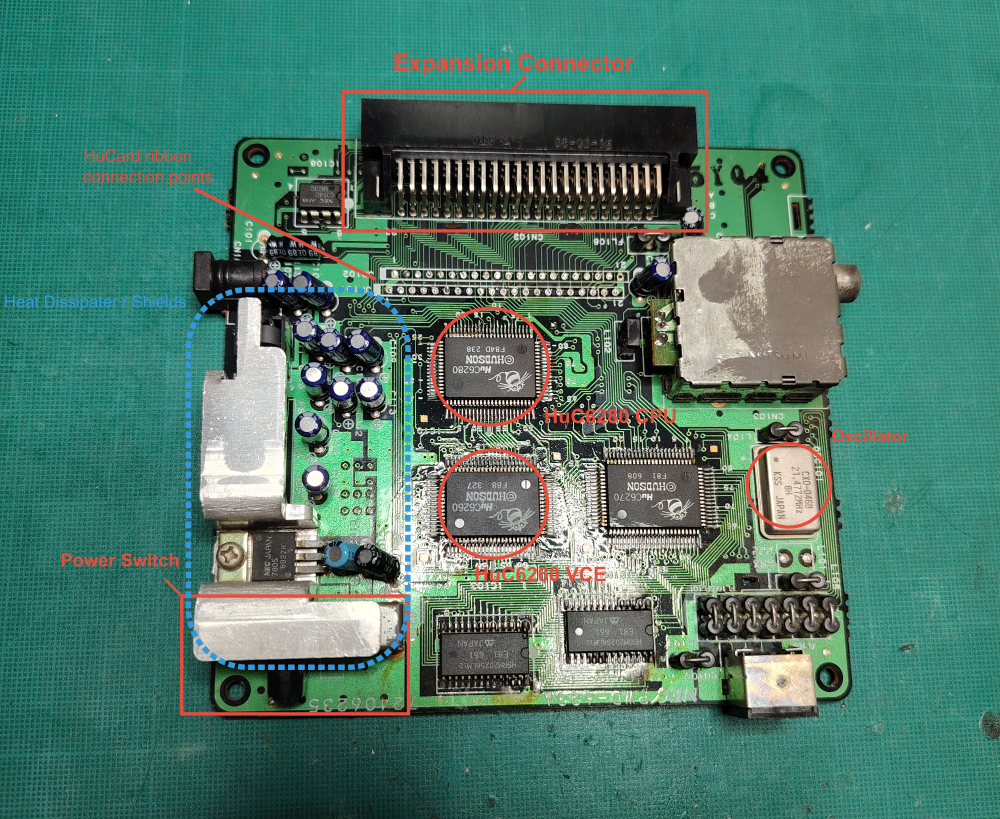
Once the ribbons are removed, de-solder and extract the following components from the original PC Engine motherboard following this order:
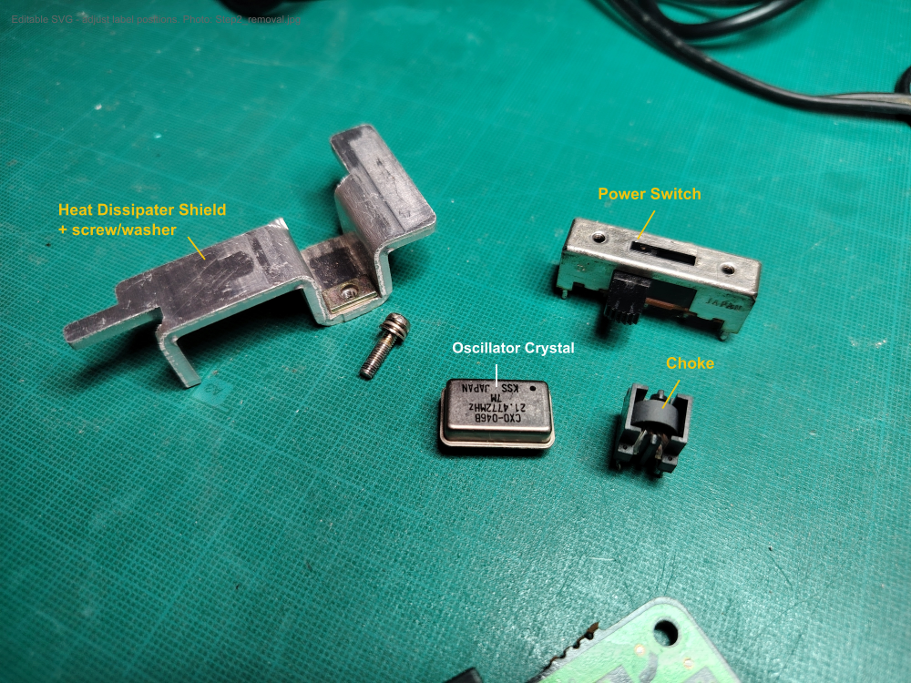
- Heat dissipater / metal shield brackets + mounting hardware (useful for mechanical fit and alignment)
- Oscillator crystal
- Choke (filter coil)
- Power switch
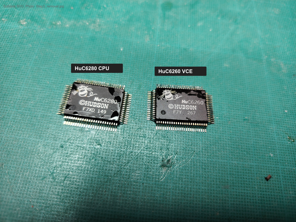
- HuC6280 CPU (surface-mount QFP)
- HuC6260 VCE (surface-mount QFP)
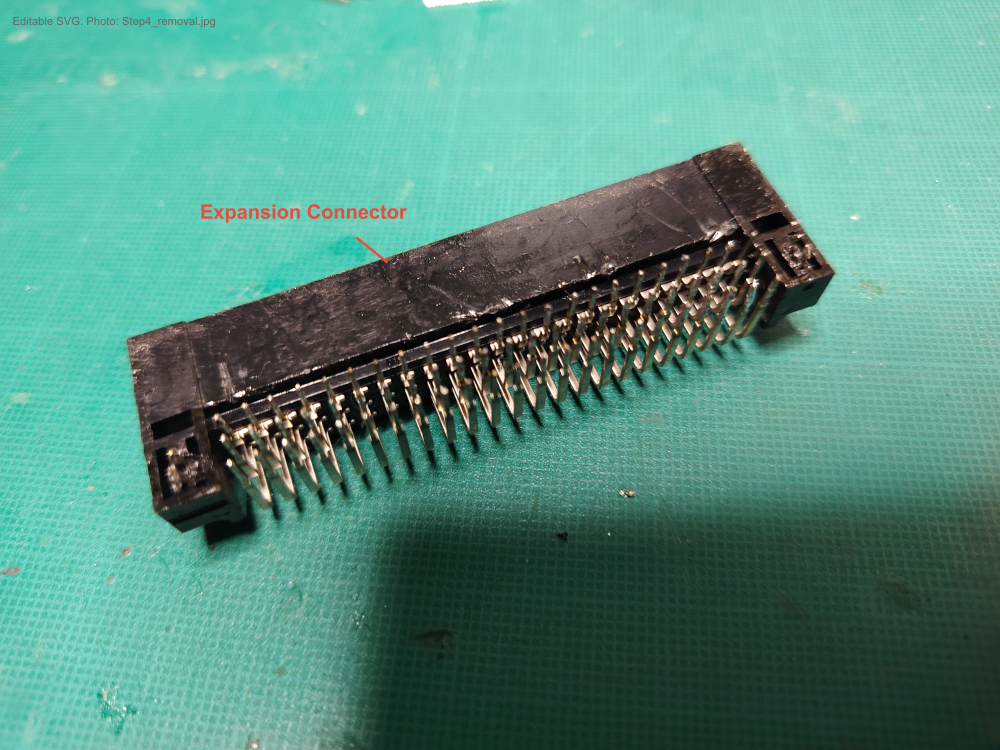
- Expansion connector (the long black connector at the top of the board) which must be done at the end as it will highly likely result in damaging the motherboard
Annotated overview of the donor board:
Extracted parts (heat dissipater shield, oscillator, power switch, and choke):
The two main ICs (surface-mount QFP packages):
Expansion connector:
Tips for this step
- The main ICs (HuC6280 and HuC6260) are surface-mount components. Use a proper de-soldering station or de-soldering braid with flux and work carefully to avoid lifting pads.
- Note the orientation of every part (pin 1 marks, crystal marking, switch pinout) before removal. Photographing the original board before you start is strongly recommended.
- Clean all pads thoroughly after removal so the parts will sit flat on the new board.
Step 2 – Populate the Polykubos SuperGrafx board
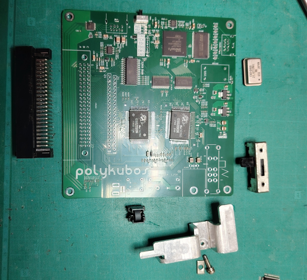
The Polykubos board arrives with most of the modern support circuitry already fitted (FPGA, voltage regulation support, SGX mode switch, upgraded Work RAM, etc.). You only need to transfer the donor parts and add a few new components that come with the kit.
Parts overview before soldering:
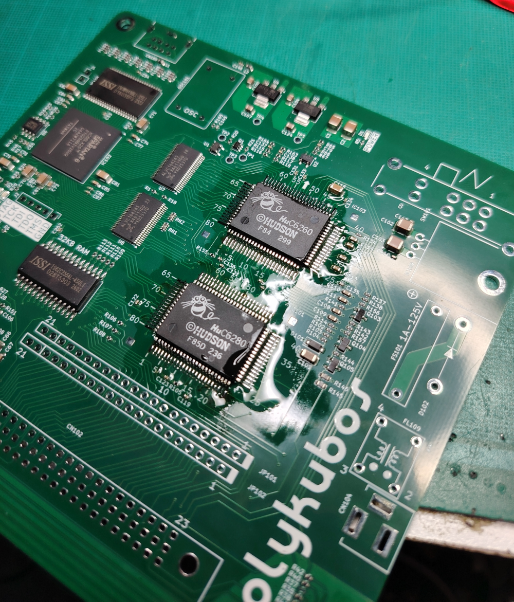
2.1 – Solder the main ICs (HuC6280 CPU and HuC6260 VCE)
These are surface-mount QFP packages. Align pin 1 carefully (the marked corner) with the silkscreen on the board, then solder. Work one side at a time and check for bridges.
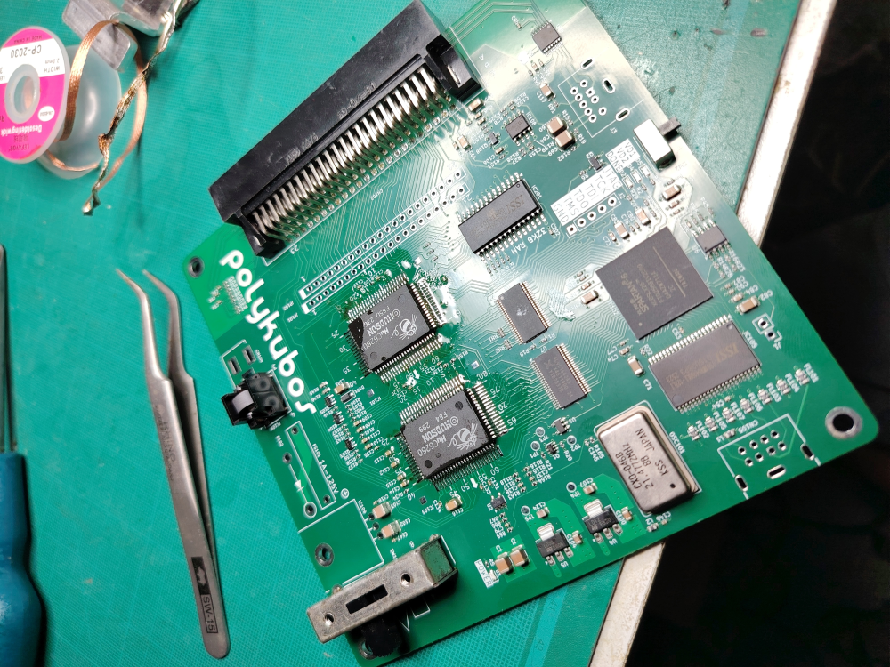
2.2 – Install the oscillator crystal, choke, and power switch
Place the 21.477 MHz crystal, the choke (filter coil), and the power switch in their marked positions and solder them.
2.3 – Add the new kit parts
The kit includes a DC power jack, diode, resettable fuse, voltage regulator, and controller port connectors. These replace or improve on the original PC Engine power section.
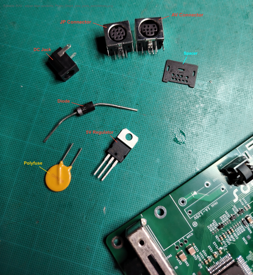
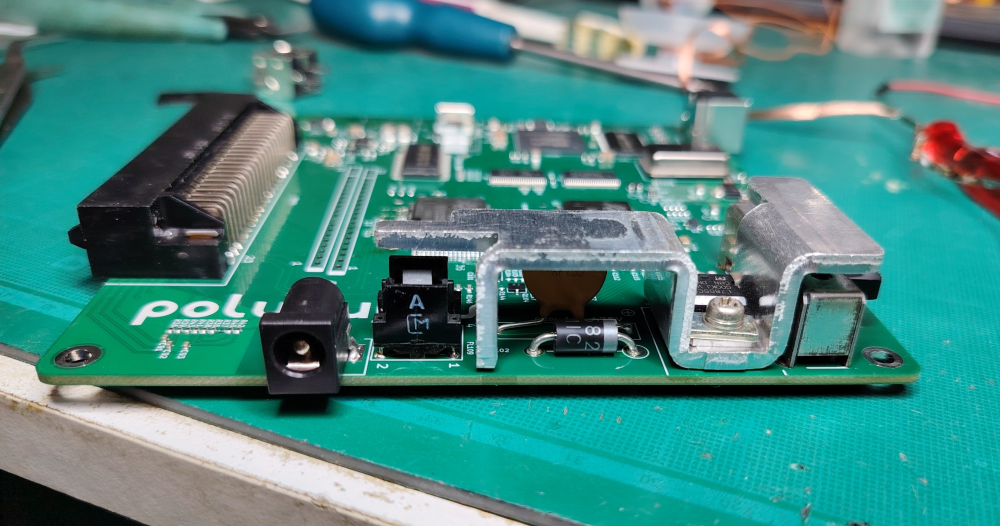
2.4 – Install the DC jack, diode, fuse, regulator, and mini-DIN joypad connector
Solder the DC input parts that sit together along the edge of the board : the jack connector, the protection diode, the resettable fuse, and the 5V regulator. New washer and nut are supplied to secure the heat sink. The mini-DIN joypad connector is visible on the opposite side of the board.
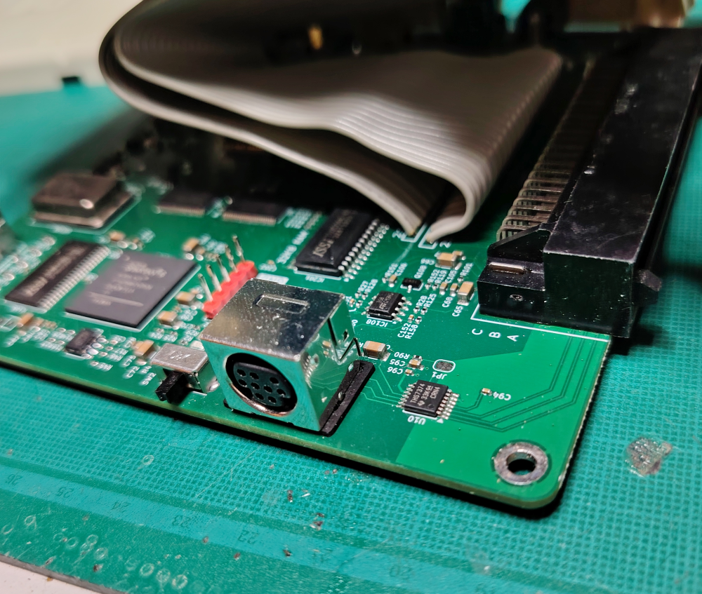
2.5 – Install the AV min-DIN connector
Solder the AV mini-DIN connector in its designated position but do not forget to include the spacer underneath it otherwise, the AV cable will be rubbing against the case. This provides the composite/RGB video and audio output. The HuCard ribbon (which is part of the next step) is visible on the picture to provide its arrangement.
Tips for Step 2
- Always confirm pin 1 orientation on the HuC6280 and HuC6260 before soldering.
- The oscillator marking should match the silkscreen.
- Use flux and a fine tip for the QFP packages. Clean flux residue afterward.
- The new DC jack, diode, and fuse improve reliability over the original PC Engine power arrangement.
- Once everything is soldered, do a clean clean of the board and carry out a visual inspection under good light before powering the board. Special care required around the 2 ICs to make sure all pins have been soldered and that there are no bridges between pins.
Step 3 – Complete the lid / HuCard assembly
This final stage prepares the original HuCard connector PCB, reinstalls it in the top case, and reconnects the ribbon cables to the Polykubos board.
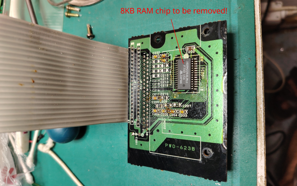
3.1 – Remove the 8 KB RAM chip
The small 8 KB RAM chip on the HuCard connector board must be removed. It is no longer needed and would interfere with the upgraded Work RAM on the Polykubos board.
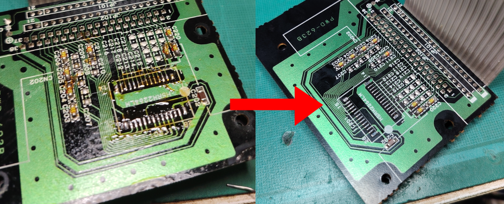
3.2 – Clean the HuCard connector board
After removing the RAM chip, thoroughly clean the board (flux residue, old solder, etc.) so the pads are ready for the ribbon cables.
3.3 – Place the PCB back into the top case
Reinstall the cleaned HuCard connector board into the original white PC Engine top case and secure it with the screws.
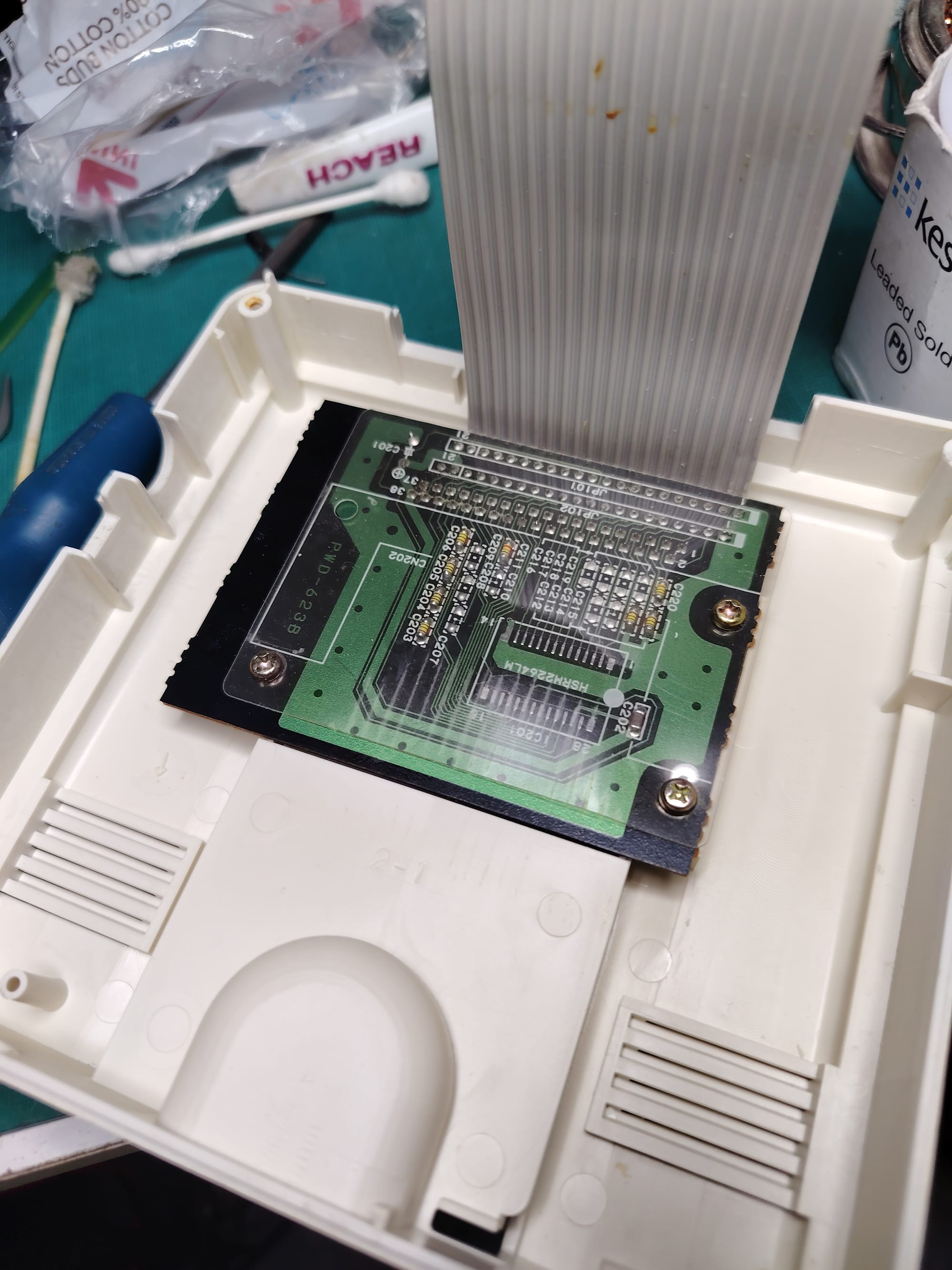
3.4 – Prepare the ribbon cables
We recommend cutting off the original contacts and stripping the ribbon cable to expose fresh conductors. This gives a cleaner, more reliable solder joint.
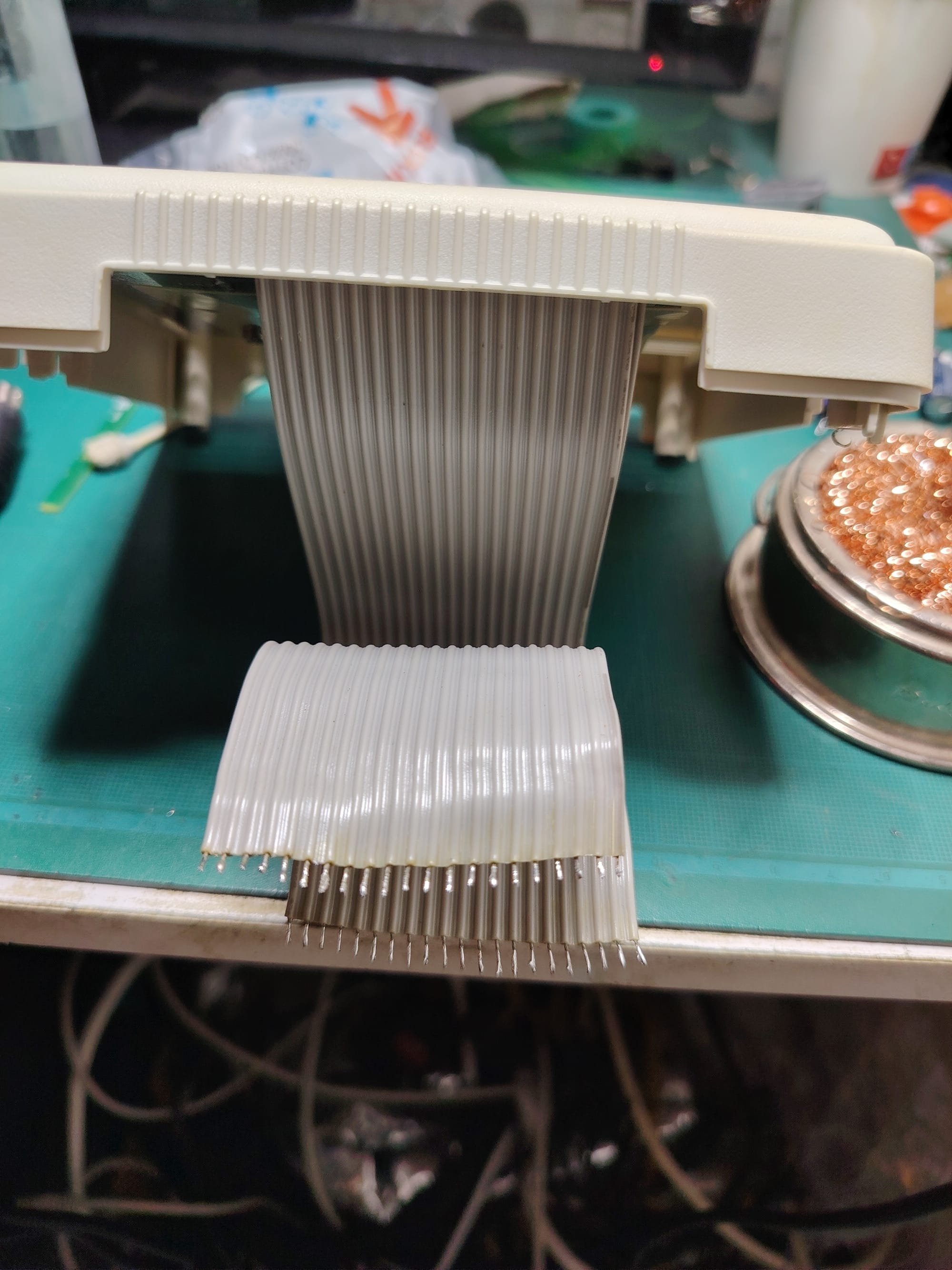
3.5 – Solder the first ribbon row
Align and solder the first row of the ribbon cable to the corresponding pads on the Polykubos board.
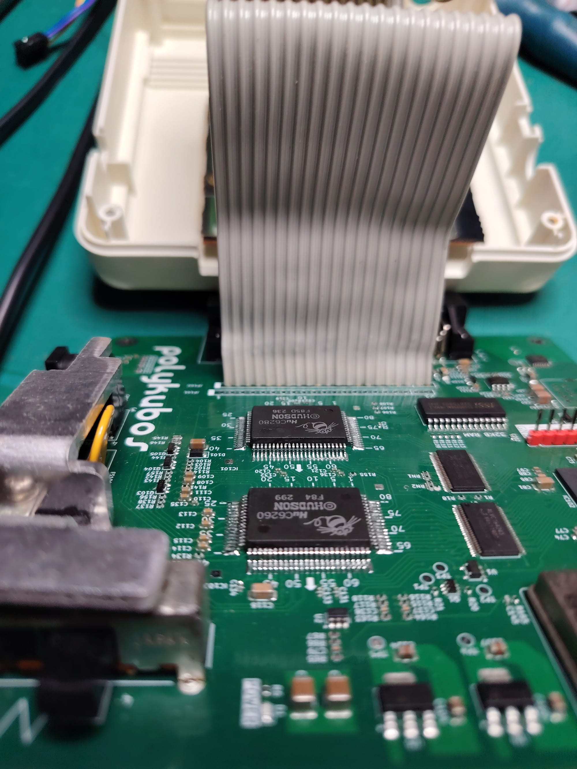
3.6 – Solder the second ribbon row
Solder the second row of the ribbon cable.
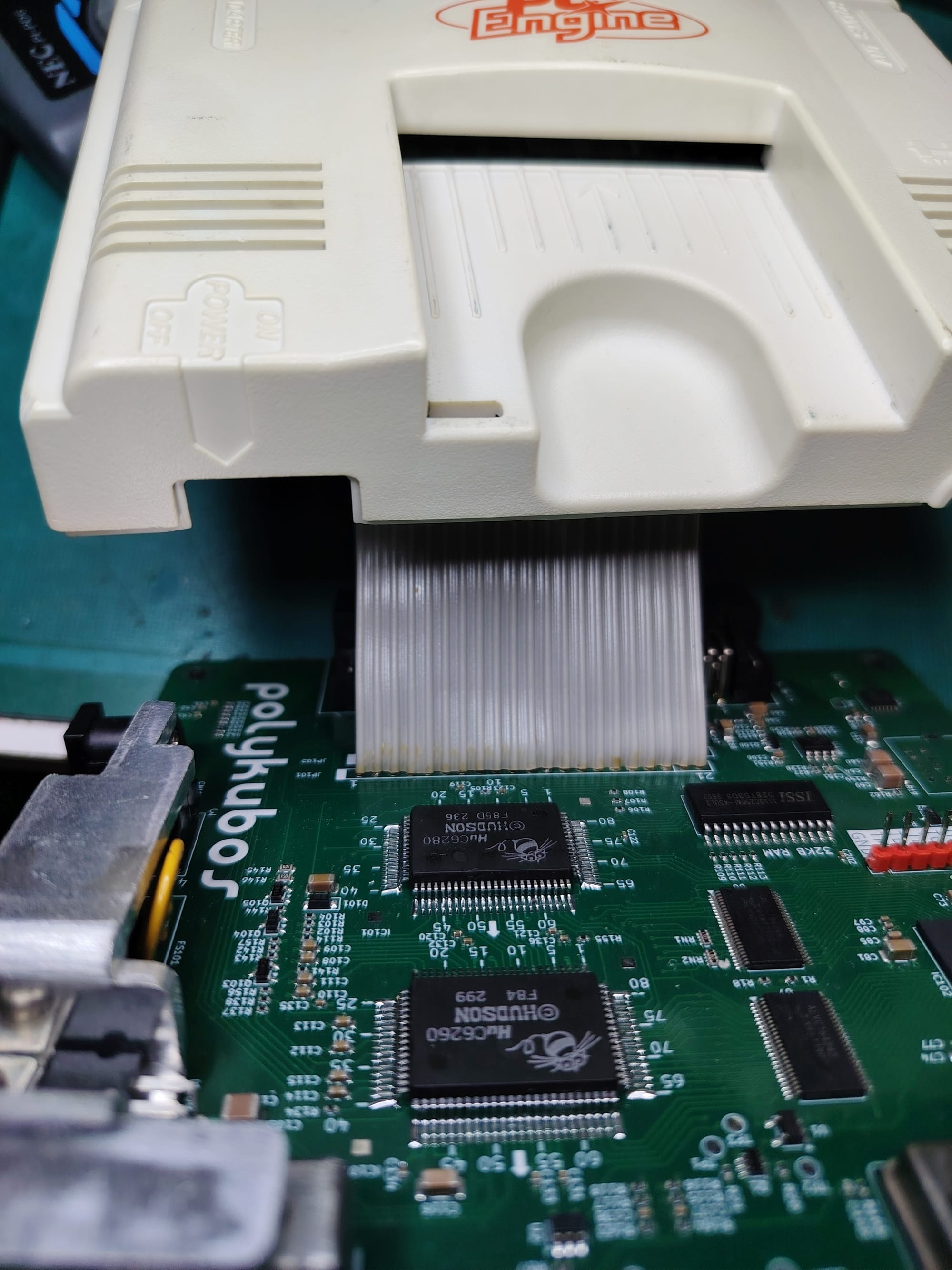
3.7 – Final visual check
Inspect both ribbon joints and the overall board before closing the case.
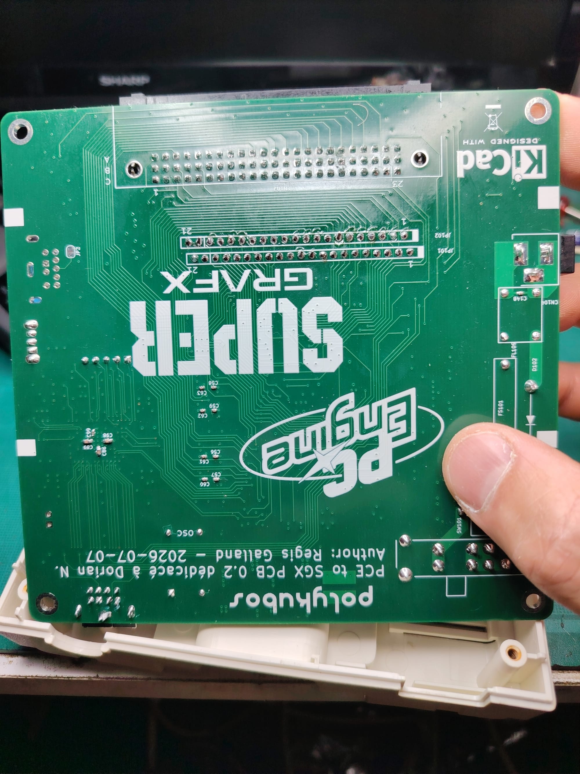
Tips for Step 3
- The 8 KB RAM chip is no longer required thanks to the upgraded Work RAM on the Polykubos board.
- Cutting and re-stripping the ribbon ends is recommended for the most reliable connection.
- Take care with the fine pitch of the ribbon pads — use flux and a fine tip.
Once both ribbons are soldered and checked, the lid can be closed and the console reassembled.